VCM-D1 Shutter Driver
Price range: $1,650.00 through $1,750.00
Current Lead Time: 4 – 5 weeks
Description
For nearly 20 years, the Uniblitz VCM-D1 has been providing high performance shutter control. This single-channel, uni-stable shutter driver is versatile and proven, and it’s compatible with many Uniblitz shutters. In addition to direct shutter control via the BNC inputs, shutters can also be controlled via RS-232C computer serial ports, allowing up to 8 separate driver units to be daisy-chained (810RJ cables required).
See the VCM-D1 User Manual for additional information regarding this device. VCM-D1 drivers built prior to August 2009 are not compatible with the 710A cable, contact us for further details.
The VCM-D1 is RoHS compliant and CE certified.
What’s Included
- VCM-D1 Shutter Driver
- Manual (included on flash drive)
- 710A Cable (3.0 m)
- 501A-S7 Adapter Cable (17.8 cm)
- Line Cords (USA and Euro)
- Fuses (2) (0.25 AMP S-B)
- Key Switch Keys (2)
Shutter Compatibility
Uni-stable Shutter Series:
CS Series: CS25, CS35, CS45, CS65H, CS90H
LS Series: LS2, LS3, LS6
VS Series: VS14, VS25, VS35
XRS Series: XRS6, XRS14, XRS25
Specifications
| System Characteristics | |
|---|---|
| Repeat Exposure | Min 35 msec between exposure for 25mm or smaller aperture shutters |
| Min 100 msec for 35mm and larger aperture shutters | |
| Shutter Drive | Continuously variable frequency of exposures from DC to the shutter in operation maximum rate |
| All BNC Inputs | Input Impedance – 4.7K Ohms |
| Active- low or Active -high selectable | |
| TTL Compatible | |
| All BNC Outputs | Source Impedance – 1K |
| Active-low or Active-high selectable | |
| TTL Compatible | |
| General | Size (HWD): 2.73×5.41×8.18 inces (69.3 x 137.4 x 207.8 mm) |
| Weight: 3.5lbs (1.59kg) | |
| Power: 115/230 VAC, 50-60Hz, 60 W | |
| RoHS compliant | |
| CE Certified | |
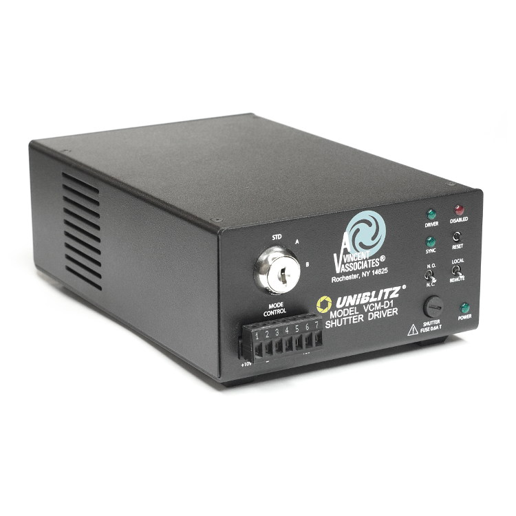
Front Panel Layout
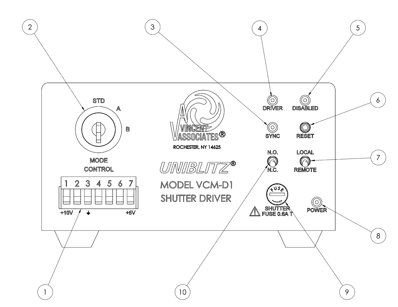
Simple and straightforward controls allow the VCM-D1 to be easy to use and configure. (See VCM-D1 user manual, starting on page 16.) LED indicators reveal shutter status at a glance, while the MODE key switch (2) will set the unit to a specific interrupt mode not allowing an inadvertent change in setting once the key is removed. Additional interrupt functions are available at the MODE CONTROL 7-PIN pluggable connector (1). The AUX output and +5VDC output are also available at the MODE CONTROL (1) terminal block.
| Front Panel | |
|---|---|
| Mode Control Terminal Block(1) | The seven-position terminal block referred to on the driver as CONTROL provides access to several of the input and output connections for external operation of your driver. Each terminal is explained in further detail in the VCM-D1 user manual, page #16. Also see pages 42-45 of the user manual for complete Input/Output specifications. |
| Mode Key Switch (2) | The position of the key switch sets the interrupt mode. It disables the shutter driver when a voltage interrupt is detected, either AC or DC. Upon reset, the shutter will return to the position set by an external input or the position of the N.O./N.C. toggle switch. |
| Sync. LED (3) | A green LED indicator that indicates status of Solid State Synchronization output. |
| Driver LED (4) | A green LED that indicates when the internal shutter driver circuit input has an active signal present. |
| Disabled LED (5) | This red LED indicates that one of the two interrupt modes has disabled the driver. |
| Reset Switch (6) | Resets VCM-D1 disabled by interrupts and returns shutter to the position determined by the N.O./ N.C. or the status of the PULSE input. |
| LOCAL / REMOTE Switch (7) | When in the LOCAL position, all I/O is effectively disconnected from the VCM-D1. When in the REMOTE position, external control of the device is restored. |
| Power indicator (8) | A green LED indicates that power is applied to the unit. |
| Shutter Fuse (9) | 5 x 20mm, 0.6A, “T” time-lag fuse to protect the shutter output |
| N.O./N.C. Switch (10) | The position of this switch determines shutter status BEFORE a trigger signal is received by the VCM-D1. |
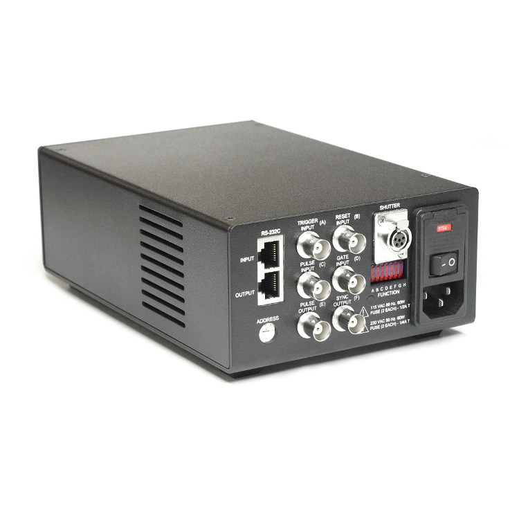
Rear Panel Layout
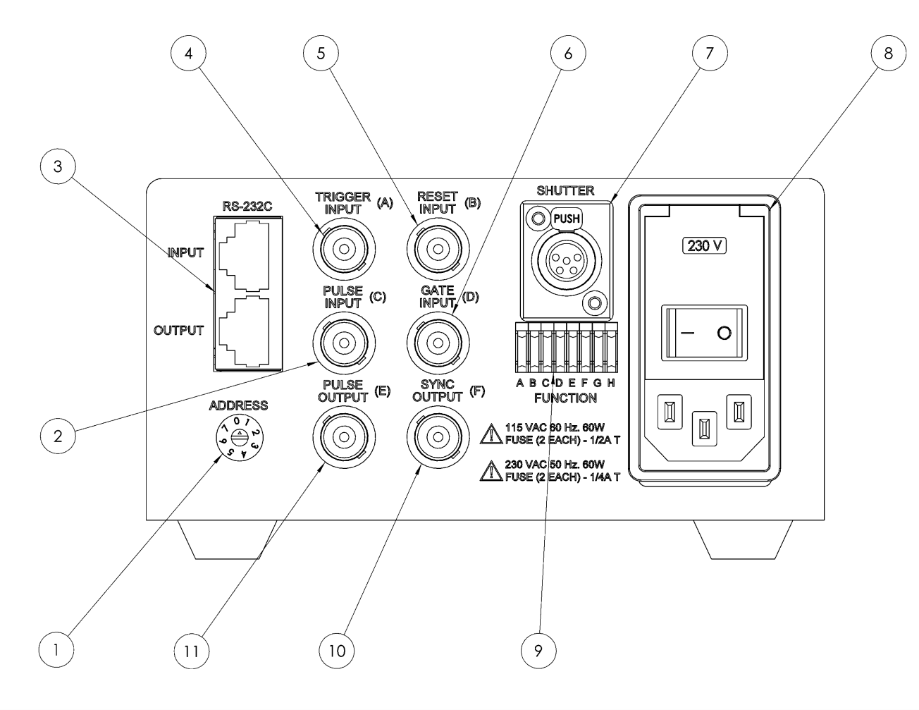
All main input/output functions can be accessed at the VCM-D1 rear panel (see VCM-D1 user manual page 21), including the 115/230VAC input (8) which is manually selectable. (See page 49 for fuse specifications and page #12 for fuse replacement instructions.) BNC connectors allow for quick termination of TTL command signals. Function switches A-F (9) determine the active state of the BNC inputs or outputs (high or low level active). Function switch H (9) selects HIGH/LOW energy level. Function switch G (9) will disable the SYNC output BNC (10) and disable the IR emitter of the synchronization circuit within the shutter used. See page #49 of the user manual for FUNCTION switch settings.
Addressable RS-232 control (3) is also available via the 8-pin RJ45 connectors. Daisy chain additional VCM-D1 units by connecting the RJ45 output of one controller to the RJ45 input of the next controller in the chain. The unit’s specific address in the chain is selected via the ADDRESS rotary octal switch (1). Shutter output (7) is a female SwitchCraft connector with locking lever. See pages 42-45 of the user manual for complete specifications, commands and address settings.
| Rear Panel | ||
|---|---|---|
| Address Select Switch (1) | Selects the active RS-232C address of the unit. | |
| Pulse Input (2) | Allows control of the shutter exposure and frequency from a TTL signal source. | |
| RS-232C Input (3) | Dual RJ45 female jack provides access to the VCM-D1 RS-232C interface. | |
| Trigger Input (4) | Allows for pulsed-open/pulsed-close shutter operation. | |
| Reset Input (5) | Returns the shutter to the position determined by the N.O./N.C. toggle switch. | |
| Gate Input (6) | The presence of an active signal will enable trigger signals presented to the Trigger Input BNC. | |
| Shutter Output (7) | Provides connection to shutter used via 5-pin female SwitchCraft™ connector. | |
| AC Input Module (8) | AC input via IEC male receptacle for AC line cord (supplied). Additional functions are described on page 26 in the VCM-D1 user manual. | |
| Function Switches (9) | Eight sub-miniature slide switches to select specific I/O and additional system characteristics described on page 26 in the VCM-D1 user manual. | |
| Sync Output (10) | Output indicates state of shutter’s electronic sync if shutter is so equipped. | |
| Pulse Output (11) | Output follows signal provided to Pulse Input (2). | |
Downloads
| Documentation | |
|---|---|
| VCM-D1 Datasheet | Download |
| VCM-D1 Manual (v 3.40 Rev A) | Download |
| VCM-D1 Declaration of Conformity | Download |
| 3D Models | |
| VCM-D1 3D Model (STEP file included in ZIP) | Download |
Additional information
| Japan Modification | No, Yes |
|---|
Related products
-
-
-
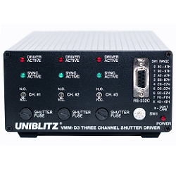
VMM-D3 Three-Channel Shutter Driver
Price range: $3,000.00 through $3,200.00Select options This product has multiple variants. The options may be chosen on the product page -