
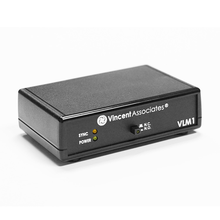
VLM1 FS Shutter Interface Module
$365.00
Current Lead Time: 3 – 4 weeks
Description
Jump to: What’s Included | Specifications | Downloads
The Uniblitz FS series shutters do not require a driver for operation (only +5V to open and 0V to close), so for applications that require remote operation of the shutter from a TTL signal or USB interface, the VLM1 Interface Module is available.
This device also offers an optional Electronic Sync interface along with a SYNC Output BNC. Additionally, the device can be operated using a USB interface which will use the computer’s power to operate the VLM1 and the attached shutter.
The VLM1 is RoHS compliant.
What’s Included
- VLM1 Interface Module
- Manual (included on flash drive)
- USB5 +5V 1A (5W) USB Power Supply
- USB A 2.0 to USB Micro B Interface Cable
- Micro Screwdriver (to install shutter leads)
Shutter Compatibility
Uni-stable Shutter Series:
FS Series: FS6, FS25, FS35
Specifications
| System Characteristics | |
|---|---|
| Power Requirements | USB /Power Input: +5VDC 0.5A min (+5VDC 1A Adapter supplied) |
| A USB interface cable is supplied for power and data when connected to a computer’s USB port. This cable can also be connected to the +5VDC power adapter (included) when a computer’s USB port is not used. | |
| Pulse Input (BNC) | Input available for control of the shutter via a +5V TTL signal – pulse width determined exposure time. |
| Active High or Active Low selectable with internal jumper. (Default – Active Low) | |
| SYNC Output (BNC) | Output available for sync output. |
| Active High or Active low output selectable with an internal jumper. (Default – Active High) | |
| Shutter Connection | A 5-pin pluggable spring terminal interconnect for shutter termination and sync system interface to the VLM1 (wire colors shown from shutter. Yellow, Green, and Blue not available on shutters without optional electronic sync system installed.) |
| Pin 1 – Shutter A (Red)
Pin 2 – Shutter B (Brown) Pin 3 – Sync System E (Yellow) Pin 4 – Sync System Return D (Green) Pin 5 – Sync System +5VDC F (Blue) |
|
| General | Size (HWD): 1.39 x 4.50 x 3.69 inches (35.3 x 114.3 x 93.5 mm) |
| LED Indicators: Green – Power. Yellow – Sync System Active (if shutter is equipped with electronic sync system) | |
| Open/Close Switch: Push to open and push to close operation. Green LED built in to the switch actuator for driver active indication. | |
| RoHS Compliant | |
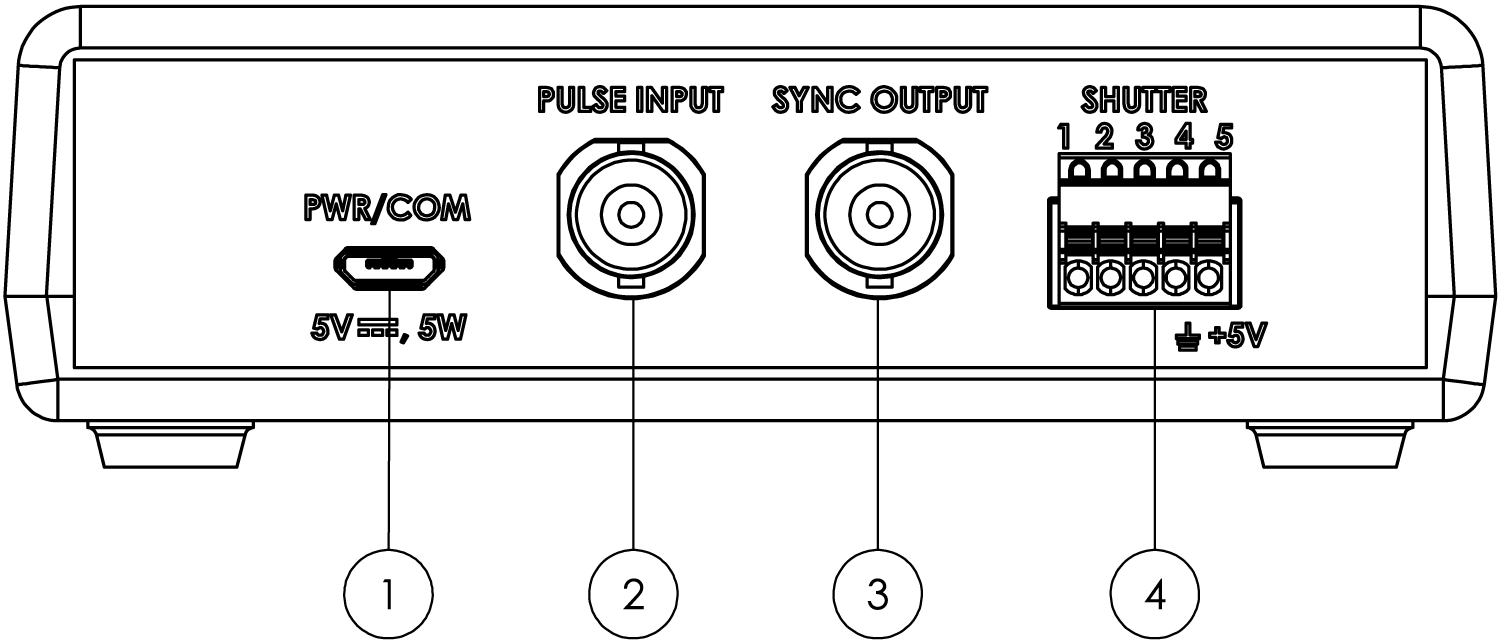
Rear Panel Layout
| Rear Panel | |
|---|---|
| USB/Power Input (1) | +5VDC 0.5A min (USB5 +5VDC 1A wall adapter included). A USB interface cable (USB A 2.0 to USB Micro B) is included for use with the USB5 power supply, or it can be connected to a computer to supply power and data. |
| Pulse Input BNC (2) | For shutter control via a +5V TTL signal – pulse width determined exposure time. Active High or Active Low (default) is selectable with an internal jumper. |
| Sync Output BNC (3) | For shutters equipped with electronic sync systems. Active High or Active Low (default) is selectable with an internal jumper. |
| 5-Pin Pluggable Spring Terminal (4) | For shutter termination and sync system interface. The flying leads from the FS series shutters can connect directly to this terminal (no adapter is necessary). |
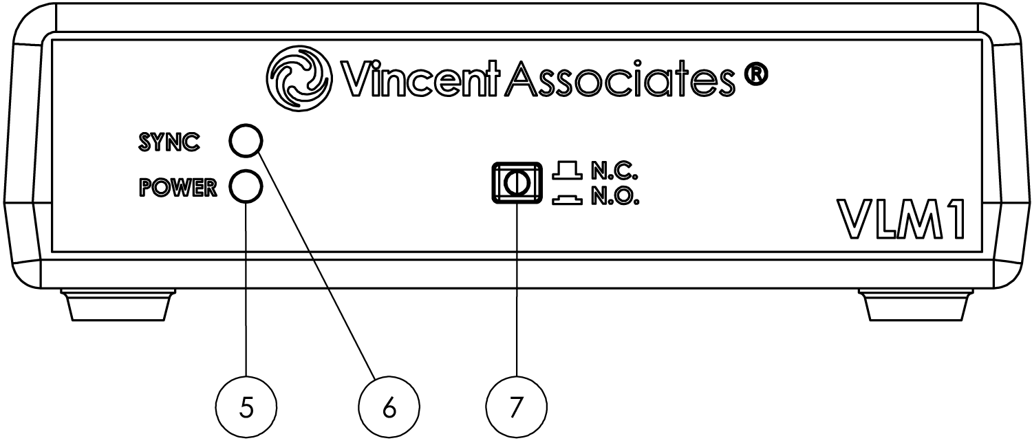
Front Panel Layout
| Front Panel | |
|---|---|
| LED Power Indicator (5) | Indicates the module’s power status. |
| LED Sync Status Indicator (6) | Indicates the module’s electronic sync status (if the attached shutter is equipped with an electronic sync system). |
| Manual Shutter Open/Close Switch (7) | Push to open and push again to close the shutter. A green LED on the push-button indicates when the driver is active. |
Downloads
| Documentation | |
|---|---|
| VLM1 Datasheet | Download |
| VLM1 Manual | Download |
Related products
-
-
VMM-D4 Four-Channel Shutter Driver
Price range: $3,000.00 through $3,200.00Select options This product has multiple variants. The options may be chosen on the product page -
-