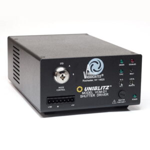

VMM-D3 Three-Channel Shutter Driver
$3,000.00 – $3,200.00
Current Lead Time: 4 – 5 weeks
Description
Jump to: What’s Included | Shutter Compatibility | Specifications | Downloads
The Uniblitz VMM-D3 is a three-channel shutter driver capable of independently controlling up to three shutters. This compact design puts three complete, individual shutter drivers in a single, streamlined package. Active high-level logic inputs allow fully independent shutter control. A single input will activate all channels simultaneously, and a single output is available to monitor when all shutter synchronization system circuits are active. Three active low-level logic outputs monitor the status of each synchronization system output. An addressable RS232-C serial input is also available to control these inputs via a computer serial port, allowing up to eight VMM-D3 units and up to 24 individual shutters to be controlled from a single computer serial port.
See the VMM-D3 User Manual for additional information regarding this device.
The VMM-D3 is RoHS compliant. It is not available for sale to the European Union. Please contact us for questions.
What’s Included
- VMM-D3 Shutter Driver
- Manual (included on flash drive)
- 710C Interconnect Cables (3) (3.0 m)
- Line Cord (USA)
- Fuses (2) (0.25 AMP S-B)
Shutter Compatibility
| CS | DSS | LS | NS | TS | VS | XRS |
|---|---|---|---|---|---|---|
| CS25 | LS2 | VS14 | XRS6 | |||
| CS35 | LS3 | VS25 | XRS14 | |||
| CS45 | LS6 | VS35 | XRS251 | |||
| CS65 | ||||||
| CS90 |
1 Will require two drive channels for operation
Don’t see your device listed above? Please contact us for information regarding the compatibility of other shutter devices.
Specifications
| System Characteristics | |
|---|---|
| Repeat Exposure | Min 50 msec between exposure for 25mm or smaller aperture shutters |
| Min 120 msec for 35mm and larger aperture shutters | |
| Shutter Drive | Continuously variable frequency of exposures from DC to the shutter in operation |
| Maximum rate detated by 75% when more than one channel in operation | |
| All Inputs | Input Impedance – 4.7K Ohms |
| Input Control | Active-High |
| Terminal Block | TTL Compatible |
| All Outputs | Source Impedance – 1K |
| Output Control | Active-Low |
| Terminal Block | TTL Compatible |
| General | Size (HWD) 2.63 x 5.35 x 8.18 inches (67.0 x 136.0 x 207.9 mm) |
| Weight 4.5 lbs (2.02kg) | |
| Power 115/230 VAC, 50-60 Hz | |
Front Panel Layout
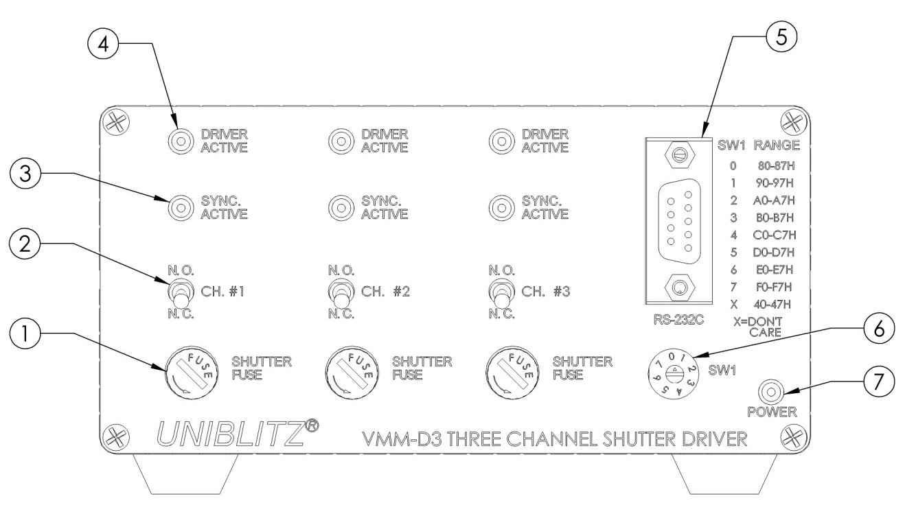
Simple and straightforward controls allow the VMM-D3 to be easy to use and configure. LED indicators reveal each shutter’s status at a glance. Three fuse holders with .6A slow blow fuses, accessible at the front panel for ease or replacement. N.O./N.C. switches allow manual shutter operation. Addressable RS-232C control is available via the DB-9 connector. Address selected by SW1.
| Front Panel | |
|---|---|
| Shutter Fuse (1) | 5 x 20mm,0.6A, “T” time-lag fuse to protect that shutter output-one for each channel. |
| N.O/N.C Switch (2) | The position of the key switch determines shutter status BEFORE a trigger signal is received by the VMM-D3-one for each channel. |
| Sync. Active LED(3) | A green LED indicator that indicates status of Solid State Synchronization output-one for each channel. |
| Driver Active LED (4) | A red LED that indicates when the internal shutter driver circuit input has an active signal present- one for each channel. |
| RS-232C Input (5) | DB-9 female connector provides access to the VMM-D3 RS-232C interface. |
| Address Select Switch-SW1 (6) | Selects the active RS-232C address of the unit. |
| Power Indicator (7) | A red LED indicates that power is applied to the unit. |
Rear Panel Layout
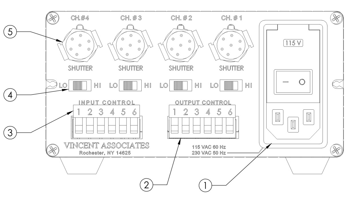
All main input/output functions can be accessed at the VMM-D3 rear panel, including the 115/230VAC input. Manual switching as required. Additionally, (2) 6-pin pluggable terminal strips allow for easy termination to input (active high) and output (active low) signals. Channel #4 output is not operational.
| Rear Panel | |
|---|---|
| AC Input Module (1) | AC input via IEC male receptical for AC line cord (supplied). Additional functions are described on page(s) 9-1, 15 and page 32 in the VMM-D3/D4 user manual. |
| Output Control (2) | Provides Electronic Sync. signal output from each shutter channel. Output indicates state of shutter’s Electronic Sync., if shutter is so equipped. One output for each channel. See terminal strip layout in VMM-D3/D4 User Manual page(s) 15-19. Active Low outputs. Output Terminal #5 – Active Low when all Sync. outputs go low. |
| Input Control (3) | Provides Active High control for each channel. Input TTL high – shutter open, input TTL low – shutter close. Terminal #5 – Active High, input TTL high – all shutters open, input TTL low – all shutters close. See terminal strip layout in VMM-D3/D4 User Manual page(s)15-19. |
| LO/HI Select Slide Switch (4) | “HI” position allows the selection of appropriate pulse energy for 35 mm and larger shutters.“LO” Position for shutters 25 mm and smaller aperture. One for each channel. Channel #4 slide switch provides no function in the VMM-D4. |
| Shutter Output (5) Channel #1-#3 | Provides connection to shutter used via 7-pin female WirePro™ connector. One for each channel. Channel #4 not operational in the VMM-D3. |
Downloads
| Documentation | |
|---|---|
| VMM-D3 Datasheet | Download |
| VMM-D3 Manual (v 2.10 Rev B) | Download |
Additional information
| Japan Modification | No, Yes |
|---|